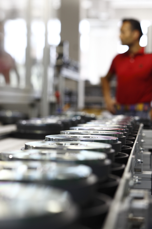
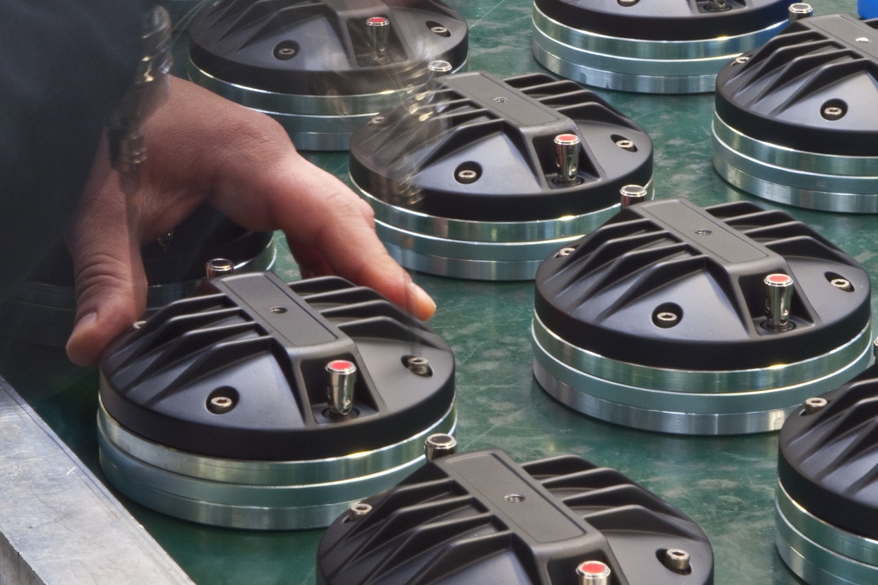
Professional loudspeaker transducers since 1946
Since 1946, B&C Speakers has been one of the largest and most prestigious professional loudspeaker transducer manufacturers in the world. In addition to designing and distributing components under the B&C brand name, they also supply OEM components to many of the top professional audio brands in the market today.
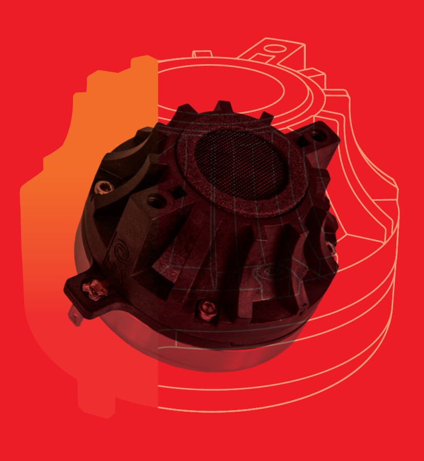
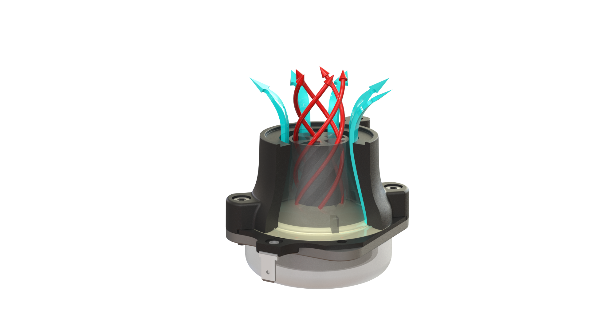
HLX™ Series
The new HLX Series compression drivers with our patented HLX™ phase plug technology provide neodymium performance at ferrite prices. Efficient material use creates surprising compactness and extended high frequency sensitivity, while boasting 4dB better mid-frequency output than any comparable driver. With the lowest distortion of any compact driver, these define a new category: the new HLX series from B&C Speakers.